
Flare testing - equations
This page contains the development of the equations using graphical means. These will be used in the "flare-it" software
Part one develops solutions at 30hz
Part two determines how the solutions change for different frequencies
Part one - Developing the 30hz equations
Background = port diameter, Foreground = frequency
Measured performance at 30hz
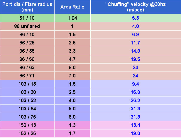
Graphing this data...
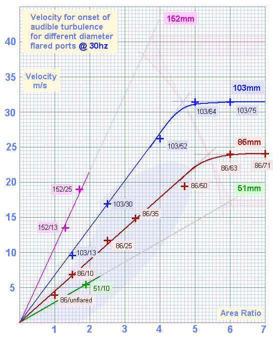
Results for all the ports @30hz
Now adding a shaded area showing an additional 40% allowance for normal music at the typical seating position.
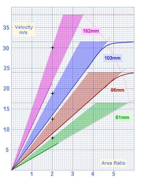
40% Allowance for distance to typical seating position, and masking effect of musical content
The first task is to identify the slope of the line for each port diameter
Picking any vertical line, ( I chose AR=2 for because there is data for each diameter ) and noting the maximum allowable velocity for each port diameter we get the following points, which are also shown on the above graph as black crosses.
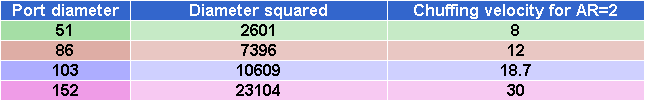
Maximum allowable velocities for various diameters at Area Ratio of 2
Diameter squared is used as the measure because it is proportional to port area,
which is proportional to carrying capacity
Graphing the points and finding the line of best fit which doesn't exceed the allowable velocity .....
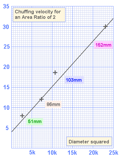
Allowable velocities at 30hz for Area Ratio of 2
Reading off from the graph...
Maximum Velocity = [3570 + ( port diameter ^ 2 )] /1785 * area ratio
Velocity is in metres per second. Port diameter and flare radius are in millimeters
Rewriting to expand area ratio in terms of diameter and flare radius...
The second task is to identify the limiting velocity for each port diameter
Reading the limiting velocities from the graph.....
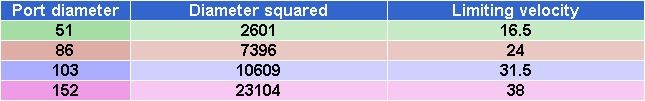
Limiting velocities for various diameters
In reality this relationship would probably be a curve, but for our purposes a segmented line is accurate enough.
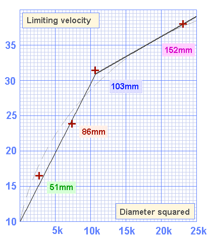
Limiting velocities at 30hz
Note: The graph and equations show the solution as chosen for use in version 2.10 of flare-it.
This is slightly different to that which was used for ver 2.00 See the version notes if more detail is required.
Reading off from the graph...
For ports smaller than 103mm in diameter
Limiting velocity = 10 +[ (diameter squared) * (19.5 / 10,000) ]
For ports larger than 103mm in diameter
Limiting velocity = 31 + [(diameter squared - 10,600) * (8.5 / 15,000)]
The next graph shows where the equations fit within the allowable ranges.
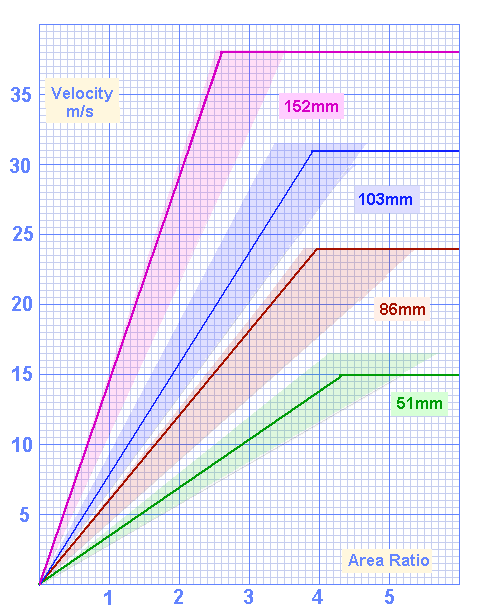
Results predicted by equations sit within allowable ranges
Note: The results for 51mm ports are a little conservative, which is desirable because it's performance is currently based on measuring a single port.
Part two - Frequency related changes to port performance
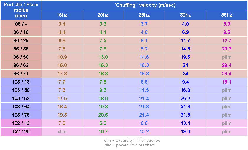
The ports were tested at 15, 20, 25, 30 and 35hz, ( power and excursion permitting )
See raw data page for actual measurements at the different frequencies
The following table summarises the relevant results:
Using a separate graph for each of the port diameters reveals how slope and limiting velocity vary with frequency...
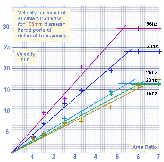
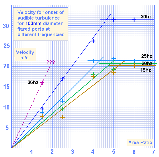
86mm diameter ports
The 86mm port results include good data for 35hz
Below 25hz, the limiting velocity doesn't fall any further.
103mm diameter ports
The 103mm ports have limited data for 35hz due to power and excursion constraints
Below 25hz, the limiting velocity doesn't fall much further.
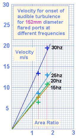
152mm diameter ports
The 152mm port could only be tested at velocities that reveal slope.
The lower frequencies were difficult to measure because of bad structural resonances.
The 160 litre box produced the highest SPL's, and at 350w, major items in the room were producing a lot of noise.
The 15hz slope is based on a single measurement, which gives a low level of accuracy, so will not be used for analysis
Measuring the variation in limiting velocity
Reading the limiting velocities from the above graphs gives the following table: The percentages indicate how much the limiting velocity changes from the 30hz figure:
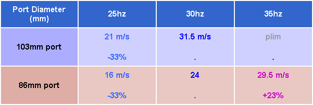
Changes in limiting velocity changes from the 30hz figure
The change appears to be independent of the port diameter, being solely determined by the frequency.
At 35hz, the limiting velocity is higher than the 30hz figure by +23%.
At 25hz, and below, the limiting velocity is lower than the 30hz figure by -33%
Measuring the variation in slope
Reading the slopes from the above graphs gives the following table
Noting the Velocity at Area Ratio = 2 allows a comparison.
The percentages indicate how much the slope changes from the 30hz figure
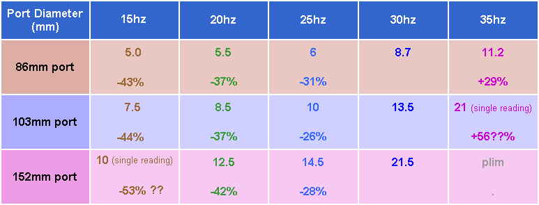
Variation in Usable velocities for AR=2 at different frequencies
Again, the change appears to be independent of the port diameter, being solely determined by the frequency.
Since the 35hz figure for the 103mm port is based on a single reading, it's best to play it safe and use the more conservative value based on the multiple readings for the 86mm ports. The same applies to the single 15hz reading for the 152mm port
For 25hz, the average is around -28%
For 20hz, the 152mm port was difficult to measure, so we'll give more weight to the 86mm and 103mm results
At 35hz, the usable velocity is higher than the 30hz figure by +29%
At 25hz, the usable velocity is lower than the 30hz figure by -28%
At 20hz, the usable velocity is lower than the 30hz figure by -37%
At 15hz, the usable velocity is lower than the 30hz figure by -44%
These results can be visualised as follows:
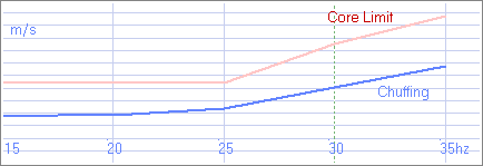
Changes in port performance with frequency