QRDude User Guide
Quick access for this page: Overview | Standard mode | The scorecard | Sightseeing | Advanced mode | Table of build depths | File association
In standard mode, the calculator can be used to design standard QRD diffuser panels. Used this way, it is much the same as the other calculators to be found on the net, except that it uses a more up-to-date method of calculating well widths, leading to better bandwidth. Its value is further extended by supporting inverse panels and providing a few more statistics.
Advanced mode unlocks the all the options, allowing the design of advanced panels using vertical and horizontal shifting, plus auto-optimise.
2D mode allows the design of 2D panels based on standard or inverse maths. Side-shifting for symmetrical panels is also supported.
Here's where to find the important stuff...
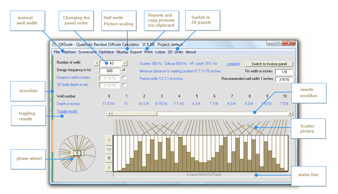
Location of controls - Advanced mode, Inverse panel
Naming conventions
To keep track of all the different design options supported by QRDude, a consistent naming and color scheme is
used inside QRDude, and in this guide
Panel order
The panel order is preceded by "N", for example "N7"
Inverse vs Non-Inverse
Inverse panels will use the prefix "Inverse", and will be dispayed in Brown
Non-Inverse panels will use the prefix "Normal", and will be dispayed in Green
Standard vs Advanced
1D panels that have been shifted vertically or horizontally are referred to as "Advanced" panels in this guide.
A panel that is vertically shifted is described in the QRDude status line as "Advanced"
Unshifted 1D panels are referred to as "Standard" panels.
Vertical and horizontal shifting for the 1D panels
Panel descriptions have the vertical and horizontal shift added to the name.
For example, N7+3,2 refers to a panel that is shifted down 3 depth units and left 2 wells.
Even if a panel is moved right, it is described in terms of the equivalent left shift.
Because Inverse panels move up as the corresponding Normal panel moves down, the vertical shifting for an Inverse panel
is described using the minus symbol rather than the plus symbol. For example, Inverse N11-4,6 refers to an
Inverse panel that is shifted up 4 depth units and left 6 wells.
Removal of fins on higher order 2D panels
The QRDude drawing for 2D panels shows the left and rear fins for finned panels.
Since the presence or absensce of fins changes the build depth for the Inverse panel only, the finless inverse is
drawn in a stronger brown color. Examples can be seen in the 2D section at the end of this guide
Units
The QRD calculator can use metric, decimal inches or fractional inches down to 1/16th of an inch.
When working in metric, recalculation takes place as you type the figures for Deepest well, Fin width or Well width.
When working in inches, the calculator waits until you press enter, or click on another active field before calculating.
As a reminder, the background color of the field is turned red, and a message is displayed in the status field
until recalculation has occurred. To change the units, click Units on the menu bar
Rounding errors
If switching backwards and forwards between metric and fractional inches, you may see a field's value change by 1mm.
The problem occurs because the smallest imperial division of 1/16th inch is not equal to the smallest metric division of 1mm,
yet the calculator has to round off to the nearest value on the new scale. For values that are right on the boundary, the
result can shift by one unit.
As an example set the fin width to 72mm. Switching to fractional inches, the nearest value is 2 13/16 inches.
Switching back, the nearest value is 71mm.
When working only in mm or inches, the issue does not arise.
Internally, QRDude works in mm, regardless of the displayed scale.
Files
QRDude.exe will attempt to create the file qrdude.ini in the same folder as the program is located.
The ini file will remember your most recent values and settings.
You can store your actual projects in any folder. If the ini file can't be read at startup,
or if a saved project can't be loaded, the default values will be used.
If for any reason the ini file becomes corrupted to the point of preventing QRDude from launching, simply delete qrdude.ini
Generating a report will attempt to create the file qrdude_1d.txt or qrdude_2d.txt, in the same folder as the program is located.
Standard mode guided tour
The easiest way to see how to use the QRD calculator is with a short walk-thru exercise...
Your first panel...
It is usual to begin with the space you have available for a diffuser. Lets say you have 150mm of depth available and
600mm of width. Furthermore, you've been to the hardware store and decided on 3mm thick fins and a 6mm thick backboard.
Fire up QRDude and because you've probably been messing with it already, set it back to the default settings using the menu
File / Reset to default values and settings
Your screen should look like this...
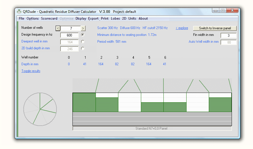
QRDude in standard mode
You want to lock in the build depth, so click the option button next to the Deepest Well field, to enable the field and turn Depthlock on.
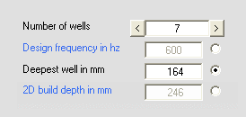
An example of turning Depthlock on
Notice that the Design Frequency caption turns blue. QRDude uses blue to indicate fields
that are calculated results and black for fields that accept user input.
Definition: From now on, the depth of the deepest well will be referred to as
the build depth.
This is how deep the finished panel will be, not counting the backboard.
You have 150mm of depth less 6mm for the backboard, so enter 144mm into the
Deepest Well field
The period width becomes 511mm and the panel frequency range is from 341Hz to 2457Hz
Panel width and period width
The period width shown is the space occupied by the wells plus the same number of fins.
Your actual finished panel width will depend on
what end treatments you need. If the extra end fin for a stand-alone panel and / or some framing is used,
you will have to manually add this.
A higher order panel
Click the right arrow next to the Number of Wells
field. The number of wells changes to 11 and the period width moves to 363mm.
We increased the number of wells but the period width got smaller!
The N11 is not as space-efficient as the N7 in terms of build depth.
Since we have locked in the build depth, the design frequency has increased and the design wavelength has decreased.
QRDude will choose a well width to ensure that the period width at least equals the design wavelength.
Since the design wavelength has decreased and the number of wells has increased,
the required well width falls from 70mm to 30mm.
Even though the design frequency has increased, the drop in well width has more than doubled the HF cutoff,
giving a better overall bandwidth
Manual well width
Since we wanted a panel 600mm wide, we will meed to manually fine-tune the well width.
Untick the menu option: "Options / Auto-minimise well width" and change the well width.
A value of 51mm gives a period width of 594mm and the frequency range is from 489Hz to 3372Hz
The nice bandwidth gains of the N11 all but dissappeared when we increased the well width. You might be tempted to build two
N11's and make them a tad smaller, so the pair fits into the 600mm space. Lets have a look...
Change the well width to 24mm. The period width is now 297mm - just what we wanted.
Can it really be that simple? ... as you might have guessed, the answer is no!
Running vertically down the left hind side of the form is a thin colored line. It was all green, but now it has
developed a red section at the top. This is known as the Scoreline.
Click it now to access the Scorecard
The scorecard
The scorecard checks the current well width against the rules for viscous losses and period width, and indicates which rule has precedence when auto-wells is active. Plate frequency and its effect on HF cutoff, if any, is also shown. Here is a the scorecard for our current example
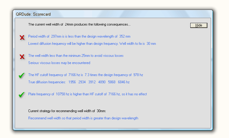
Scorecard screen
From the scorecard, we can see that decreasing the well width below the recommended value has produced a period width violation.
This problem tends to go away with higher order panels.
The second line checks the well width against the viscous limit. In this case, it shows a serious warning that the well width
is less than 25mm.
This is the minimum acceptable well width to avoid viscous losses, and should not be ignored.
The exception is when you're designing a well insert, where the much shallower build allows narrower wells.
For panels deeper than 400mm, this 25mm minimum width is scaled up to build depth divided by 16.
The calculation is based on the deepest of the normal and inverse panels, and the result applied
to both panels.
This is done, even when pairing is not selected, in order to keep the panel widths the same
when toggling between the two types.
By the time panel order is large enough for the viscous limit to over-ride the period width limit on very deep panels,
the difference in build depth between normal and inverse panels is not overly large.
The small compromise of using the one viscous limit for unpaired normal and inverse panels saves having yet
another restriction on toggling.
The third line lists the frequencies at which true diffusion occurs. These are multiples of the design frequency
and the list removes any that are not valid due to period width or plate frequency infractions.
If you wish, you can leave the scorecard open whilst you continue working. You may not need to though because
the scoreline makes it so easy to access when needed.
The scoreline is divided into four segments, and the color of the segments corresponds to color of the ticks on the scorecard.
An alternative way to display the scorecard is by clicking on the Scorecard
menu option.
Shortcut: Changing the number of wells
It would take a lot of clicking on the right arrow to get up to say, 71 wells. Here is a shortcut. Put in a number that is close to what you are looking for, If it is not prime, the status line will let you know, and re-calculation will not occur. Now click the arrow. QRDude will automatically seek to the next available prime number
Turn auto-minimise well width back on and play with some of the higher order panels.
Look at how the bandwidth increases as the order goes up, without the panel width changing by much. Once the well width
gets down to the viscous limit, the panel size starts to grow.
If you have a target panel width, you will need to use manual well widths, but the principle will still be the same.
The matching inverse panel
Because the inverse panel will have a different build depth, and must have the same design frequency,
you need to release the depthlock, so click the option button next to the Design frequency field
Switching between normal and inverse panels is disabled when depthlock is on
A normal panel and it's corresponding inverse nearly always have different build depths
If the inverse toggle was available when depthlock is on, the frequency would shift when you change
to the inverse - ie not the correct inverse panel for the normal panel you just came from!
To prevent this from occurring , clicking the Switch to inverse panel button will result
in a warning message when depthlock is on.
To switch between normal and inverse panels in this situation, you must turn off depthlock first.
Once in inverse mode, you can put depthlock back on and play to your heart's desire.
When switching back to the normal panel, again after turning off depthlock,
you will find that the normal panel is the correct mirror to the inverse panel you just came from.
Click the Switch to inverse panel button to display the inverse panel. The design frequency and width are the same as the normal panel, but the build depth
has increased. If you are wanting to build an array of panels that includes an inverse, you
will need to set the depth back to your required value
Release the depth lock again and switch back to the normal panel. The build depth for the normal panel is now smaller again.
Half-wells
With a standard panel, the well on left-hand end is always zero-depth. By moving half of this well to the right hand side of the panel, you get a symmetrical panel as shown here. When two units are placed side-by-side, this gives one full well. Note that the half-well option is no use if you are abutting an inverse panel, as the end well on the inverse is not zero-depth.

A pair of N7 QRD panels using the half-well ends
Try it now on your sample project. From the menu, select
Display / When 1st well is zero-depth, show panel moved left half a well for a symmetrical build

After checking out the display picture, turn if off again.
Visualiser
A new feature for Version 4.0 of QRDude is the Visualiser screen. This allows you to see how a group of panels look when viewed from the front. As you can see from the menu below, you can visualise up to three panels in various arrangements.
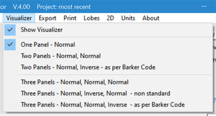
Visualiser Submenu
Clicking on the "Show Visualiser" option in the menu will bring up the Visualiser screen.

Visualiser showing three N29 panels - two normal and one inverse as per the barker code
The visualiser screen is resizable, with the image recalculating on the fly. If you "throw" the form to the top left corner of the screen, it will maximise.
This will obscure the main form, but as prompted in the form titlebar, pressing "ALT-Tab" will return the main form to the front.
As you make changes on the mainform, the Visualiser will continue to reflect these changes.
Double-clicking on the Visualiser screen will copy the image to the Clipboard.
One interesting thing that can be seen with this screen is what happens when you rotate the phase wheeel in the main form (Advanced Mode neeeds to be ticked),
the normal panels move downwards.
If the Visualiser is showing a mix of normal and inverse panels, the inverse panels move upwards.
If you were wanting to make the join between a normal and an inverse panel to appear seamless,
you can use this method to "walk them towards each other."
For information on using the Barker code to place inverse panels in the correct sequence, see the QRDude Technical Reference
When you are finished with the screen, Clicking on the "Show Visualiser" option again will untick the option and hide the screen.
Fin width
Fin width can be tweaked to get a panel of a particular size. To be effective, you may need to turn auto-minimise well width off. If you don't do this, and the well width is greater than 25mm, you'll find that QRDude changes the well width to keep the period width above the design wavelength. As a result, the panel size doesn't change by much, but the HF cutoff frequency does. Take care to ensure that the fin width is always small compared to the well width.
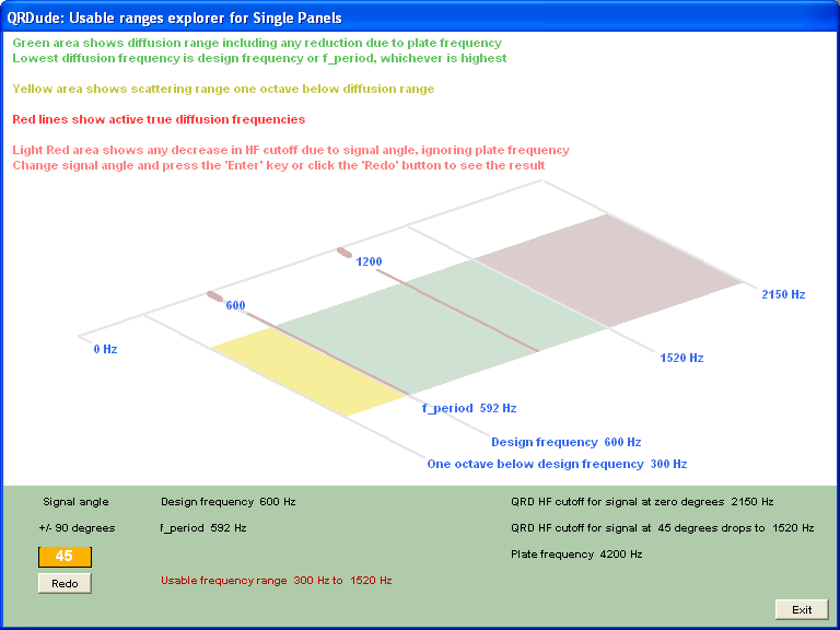
Usable ranges explorer
The Usable ranges explorer is new for Version 3 and is accessible from
the 'explore' link located at the right of the frequency ranges field on the main screen.

The screen allows a visualisation of the scattering and diffusion ranges for a single panel, and can model the change
in HF cutoff frequency as the signal angle of incidence is changed. See the feature panel on the qrd overview page for a
detailed explanation as to why this occcurs.
The consequences for panels at first reflection points are worth considering.
A bit of sightseeing...
Toggle results
Clicking on the Toggle results label will cycle the way the results for
well depths are displayed.
Available are: Depth in mm (or inches), Block heights in mm (or inches), Phase shift in degrees, and ratio (depth in depth units)
If you hover the mouse over the drawing of the panel, a pop-up tooltip will provide information about the well
directly under the mouse

Tooltips showing details for well under mouse current position
Phase wheel
Each colored spoke on the phase wheel show the amount of phase shift introduced by one or more wells.
The spokes shown in light grey represent positions not used in the current panel.
Also note that the phase wheel for the inverse panel is the mirror image of that for the standard panel.
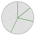
Phase wheel (N7 panel, standard mode)
Scatter picture
The scatter pictures are an easy way to see how the diffusion angles change with different panels. The lines are calculated
using the well depths either side of the fins and are a visual representation only, they do not show the exact
diffusion pattern which would be much more complex. They are particularly useful when it comes to understanding advanced panels,
and when comparing prospective panels for use in Barker modulation schemes.
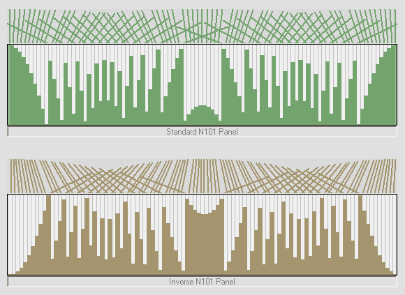
Scatter pictures compared (fins edited for clarity)
Scaling the drawing
By default the panel picture is stretched to fill the drawing to give the clearest view. The correct shape can be seen by selecting
one of the options to draw the picture to scale. Since the size varies considerably as the number of wells increases and/or
design frequency changes, four scaling sizes are offered.
Access the choice via the Display menu
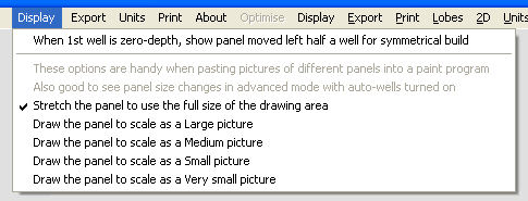
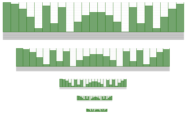
Scaling options compared: Stretched, To-scale Large, Medium, Small, Very small
Export
The Export menu is a convenient way to get information out of QRDude.

Shortcut: You can also Double-click on any of these images to copy it to the Clipboard.
The first option will create the text file qrdude_1d.txt
containing all the values, results and scorecard information.
QRDude will then attempt to open this file in your default text editor (normally notepad)
The other three options will copy the associated picture to the clipboard. A shortcut to using the menu is to double-click
the picture. All the drawings of panels in this writeup were generated using this process.
The main intended use for the facility is to paste to-scale panels into a paint program for easy assembly of Barker sequences,
as shown in this next example.

Barker sequence of three N13 panels and one I13 panel
Pimping the QRD - advanced mode
The advanced mode of QRDude allows the production of panels with more variations than the original designs.
These allow additional choices for panel depths, widths and bandwidths, yet all are valid QRD panels.
This brings us to the heart of why QRDude was written
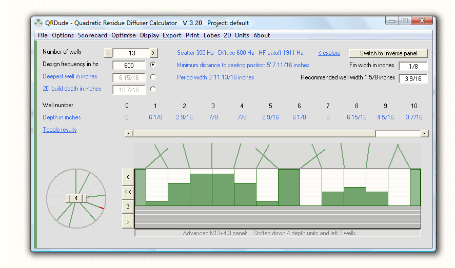
An example of Advanced Mode using imperial units.
For designing custom QRD diffusers, advanced mode provides three new features:
- Using the phase wheel to rotate the panel downwards
- Smarter well depths using the Auto-optimise option
- Shifting the panel sideways
The following controls become active under advanced mode...
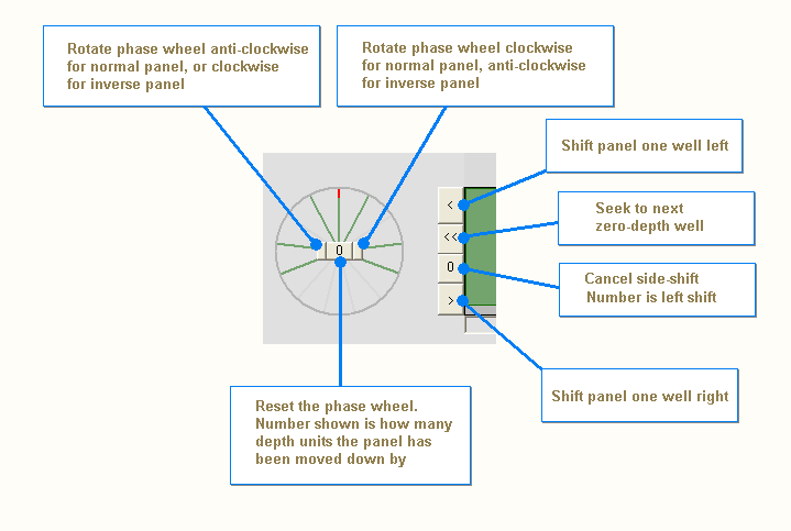
Additional controls for advanced mode
Using the phase wheel to rotate the panel downwards
As stated at the top of the page, the classic equation for determining the depths of the individual well is:
Depth = (well position)^2 mod N
... where N equals the number of wells, and is a prime number
Advanced mode exploits the fact that valid panels can also be produced by adding a number inside the modulus part:
Depth = ((well position)^2
+ V
) mod N
... where V is a whole number
You can read more about
this variation
in the book : Acoustic absorbers and diffusers: theory, design, and application By Trevor J. Cox, Peter D'Antonio
In essence, V is the number of depth units that the standard panel is moved downward.
The principle is best understood by examining all the variations for an N7 panel...
Firstly, the standard N7 panel, where V=0

Standard N7 panel and its inverse
Each of the spokes on the phase wheel represents one of the possible phase shifts introduced by a well of the diffuser.
There are the same number of spokes as there are wells, so for example an N7 diffuser has 7 wells, so the wheel has 7 spokes.
A spoke that represents a phase shift that is produced by one or more wells is shown as solid / green.
A spoke that represents a phase shift that is not produced by any of the wells is shown as ghosted / grey.
The red tip shows the amount of phase shift for the first well in both panels. This makes it easier to visualise the panel as the wheel is rotated.
For the standard panel, the first well introduces a phase shift of zero degrees, so the tip is at 12 o'clock on the wheel.
The first well of the inverse panel introduces a phase shift of 360 degrees. Since this is equivalent to zero degrees, it is also shown at 12 o'clock on its wheel.
The normal panel is drawn in green and the inverse panel is shown in brown. Remember that for the inverse panel, the depth of each well is equal
to the order of the panel (ie N number) minus the depth of the corresponding well in the normal panel.
This gives a range of 0 to N-1 for the normal panel, and 1 to N for the inverse panel.
As the phase wheel for the standard panel is rotated clockwise, the wheel for the inverse panel rotates anti-clockwise
Next, the situation with V=1

N7+1 panel and its inverse
The normal panel has been moved down one depth unit, and its phase wheel has been rotated clockwise by one position.
The inverse panel has been moved up one depth unit, and its phase wheel has been rotated anti-clockwise by one position.
Already, the use of the Advanced mode has produced some consequences:
- The build depth for the inverse panel is now less than the design depth. For a sequence of normal and inverse panels, utilising a given available depth, the design frequency can be lowered.
- The normal panel no longer has any wells with zero-depth. This can also be seen on the phase wheel, where the 12 o'clock position is unoccupied. The main result of this, is that this particular panel cannot be built with half-width wells on each end.
Next, the situation with V=2

N7+2 panel and its inverse
As the panel and its inverse continue their march in opposite directions, the build depth of the inverse panel is now actually less than its normal partner. This is the shallowest you can build the N7 inverse panel.
Next, the situation with V=3

N7+3 panel and its inverse
Woah! Something has happened!
The well at position three of the normal panel should be at the maximum depth. However, because the depth range for the
normal panel is zero to N-1, this is not allowed.
Since 7 mod 7 = 0, this well becomes zero depth.
Similar logic applies to the same well of the inverse panel. It was on its way up, and was due to occupy the
zero-depth position. The allowable range for the inverse panel is from 1 to N, therefore a zero-depth position is not allowed.
It converts into an N depth position, as shown.
Up until now, the well depths have stayed in step as the wells are moved downwards. It is as if the same panel has been
mounted one depth unit closer to the wall each time the phase wheel has been rotated.
With this panel, the relative position of the third well with its neighbors has changed,
resulting in a new panel with different diffusion angles.
This happens each time a green spoke arrives at the 12 o'clock position of the phase wheel
Next, the situation with V=4

N7+4 panel and its inverse
In this arrangement, the build depths for the panel and its inverse are the same. Possibly the best arrangement for using multiple normal panels along with the occasional inverse panel in a Barker sequence.
Next, the situation with V=5

N7+5 panel and its inverse
The fourth and fifth wells have flipped, meaning another new panel
Lastly, the situation with V=6

N7+6 panel and its inverse
The second and seventh wells have flipped, meaning yet another new panel
Note: Changing the number of wells resets phase wheel rotation
Maximum depth saving at a glance
The advanced mode relies on finding the vertical section of the panel that has the most continuous unused depth units
Here is the phase wheel for a standard N13 panel. The area of interest has been highlighted in red and comprises five segments.

If the phase wheel is rotated to bring this zone up to just before the 12 o'clock position, all these unused depths will be sitting nicely at the bottom of the panel, thusly...

Here's how it looks in 3D...
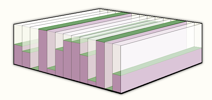
N13+4 panel
When examining a panel of any order, find the most continuous segments without a green spoke,
and that will tell you the biggest depth saving possible.
Note that this maximum saving is for a stand-alone panel. If you are pairing a panel with it's inverse, you will want
to share the saving with the inverse panel.
In that case the free segments should be centred around the 12 o'clock position.
If there is an even number of continuous free segments, you will be able to get an exact match for the build depth of the two
panels, otherwise the closest you can get is one depth unit. (See the N7+4 example in the previous section)
If you're feeling a bit overwhelmed by all this, don't dispair. It's about to get a whole lot easier...
Build depth optimising
As the previous section showed, rotating the phase wheel can often yield a shallower panel. The best build option for each of the normal panels supported by QRDude has been collected into the following table. As you can see, the best savings are in the lower order panels.
The table shows build depth as a percentage of design depth, for standard panels, and for stand-alone advanced panels
with the smallest build depth.
The last column shows the improvement as a percentage of the standard panel build depth
| Standard | Build depth % | Advanced | Build depth % | Improvement % |
| N3 | 33 | N3 | 33 | 0 |
| N5 | 80 | N5+1 | 40 | 50 |
| N7 | 57 | N7 | 57 | 0 |
| N11 | 82 | N11+2 | 64 | 22 |
| N13 | 92 | N13+4 | 62 | 33 |
| N17 | 94 | N17+4 | 77 | 18 |
| N19 | 90 | N19+3 | 74 | 18 |
| N23 | 78 | N23 | 78 | 0 |
| N29 | 97 | N29+9 | 86 | 11 |
| N31 | 90 | N31+6 | 84 | 7 |
| N37 | 97 | N37+16 | 87 | 10 |
| N41 | 98 | N41+10 | 85 | 13 |
| N43 | 95 | N43+12 | 86 | 9 |
| N47 | 89 | N47 | 89 | 0 |
| N53 | 98 | N53+17 | 87 | 11 |
| N59 | 97 | N59+24 | 90 | 8 |
| N61 | 98 | N61+27 | 89 | 9 |
| N67 | 97 | N67+20 | 90 | 8 |
| N71 | 90 | N71 | 90 | 0 |
| N73 | 99 | N73+27 | 93 | 6 |
| N79 | 96 | N79+17 | 91 | 5 |
| N83 | 98 | N83+24 | 91 | 7 |
| N89 | 99 | N89+25 | 92 | 7 |
| N97 | 99 | N97+36 | 93 | 6 |
| N101 | 99 | N101+37 | 94 | 3 |
This table, along with one for inverse panels, and another for paired panels,
has been built in to QRDude.
In advanced mode, you can click on the
Optimise menu entry to go direct to the most economical build depth.
The behaviour depends on whether you are pairing with an inverse panel
Specifying stand-alone or paired is done via the menu option:
"Options / 1D Panel will be used in a sequence that includes its inverse"
This menu option only has an effect in Advanced mode, so it is disabled at other times
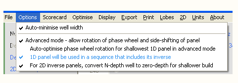
- If you have specified a normal stand-alone panel, the arrangements will be as per the table.
- If you are working with stand-alone inverse panels, (ie you have decoupled the pairing with the normal panel), the build depth will be optimised using a different table. Note that because of the decoupling, this panel is NOT a matching inverse for an optimised normal panel of the same order.
- If you are paired with an inverse panel, the saving is split between the two panels to give the least build depth for the combination. Where build depths are not the same, the inverse is set to be the deepest.
Of course there can be some compromises when using depth optimisation to lower design frequency
The physical width of the panel needs to be equal to or greater than the period width (approximately the desigh wavelength).
In practical terms, if you lower the the design frequency using depth optimisation, the required panel width will increase.
For panels with a lot of wells, the panel will already be wide enough to meet this condition.
For smaller panels, say N<19 with a design frequency around 1000hz or lower, the auto-well-width feature (if ticked) will increase the well width
till the panel width passes the period width requirement.
The wider wells cause the upper cutoff freqiency to be lower.
To summarise:
For lower order panels, using build depth optimising can result in an increase in panel width and a decrease in upper frequency cutoff.
This can be avoided by using a higher order panel that is already wide enough for the lower design frequency.
Build depth optimising can be set to automatic
This is activated via the menu option: Options / Auto-optimise phase wheel rotation
for shallowest 1D panel in advanced mode (turned off by default)
This menu option only has an effect in Advanced mode, so it is disabled at other times
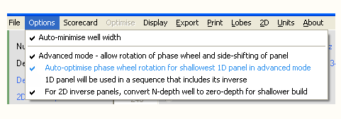
When auto-optimise is on, manual rotation of the phase wheel is disabled:
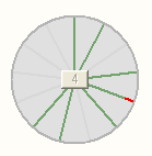
As for manual optimisation, the resulting depth depends on whether you are pairing with an inverse panel
There is a further consequence of using auto-optimise, and it concerns toggling between normal and inverse panels.
There are two possibilities:
- Pairing is turned off (default setting). In this situation, you are prevented from toggling between the normal and inverse panels (in either direction). Allowing the toggle would give a normal panel that is auto-optimised as a stand-alone panel, and an inverse panel that is also auto-optimised as a stand-alone panel. The two panels would not have a correct inverse relationship. If you wish to toggle, you need to either turn off auto-optimise, or tick the pairing option.
- Pairing is turned on. Because both panels are considered in the optimisation, the two panels will have a correct inverse relationship. Toggling is allowed.
Shifting the panel sideways
After designing a panel that is vertically shifted, you may find there is no zero-depth well on the left end, but there
is one or more elsewhere in the sequence.
Here is the N13 panel from the previous example shifted left by three wells, allowing half-width end wells

N13+4,3 panel with half-width end wells
The buttons on the lefthand end of the picture (only visible in Advanced mode) control the sideways shifting. Since redraw is slow for the higher order panels, shifting one well at a time takes ages. Use the button with the double arrows to seek to the next zero-depth well. The button with the number on it shows the number of wells the panel is left-shifted. It is also a reset button - clicking it will set the shift back to zero.
Note: phase wheel rotation resets side shift.
Note: Changing the number of wells resets both phase wheel rotation and side shift
Installation tip
File association
Associating qrdude.exe with the .qrd extension allows you to double-click on a saved qrd file and launch
qrdude with that file loaded.
Here's how to do it in Windows XP...(different versions may vary slightly)
- Run QRDude and save a file using File / Save from the menu. Close QRDude
- Open Windows File Explorer and navigate to the .qrd file you just created
- As shown in the following screenshot, right-click on the file
- A menu appears - click on Open With
- A sub-menu appears - click on Choose Program
- The "Open With" selection screen appears - tick Always use the selected program to open this kind of file
- Click the Browse button
- An explorer window will open - navigate to where you put qrdude.exe and double-click it
- You will be returned to the selection screen - click the OK button to complete the process
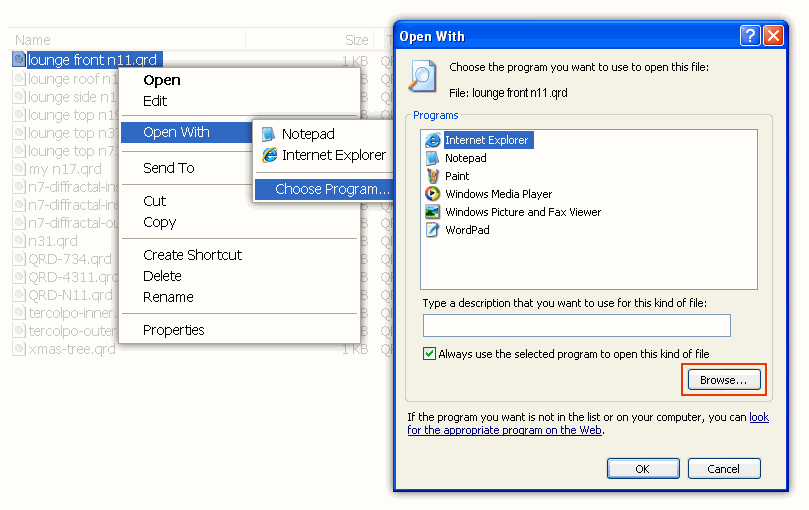
File Association supported from version 2.05 onward
Additional QRDude pages:
