Concentric Port Construction Gallery
Cutting Disks
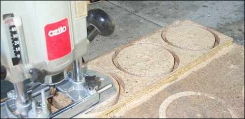
The router is used to cut the disks for the jig. Screw the disks to the board underneath to stop them moving when you cut the last bit out
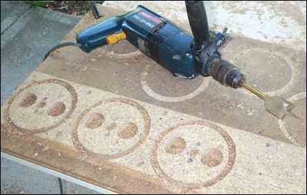
Access holes
A speedbore type drill bit can cut some holes in the disks. These make it easier to unscrew the disks after a tube has been epoxied. It the tube is too tight, the holes make it easier to break the disks into halves for removal
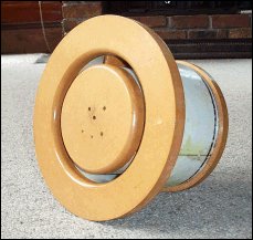
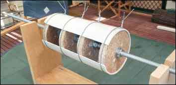
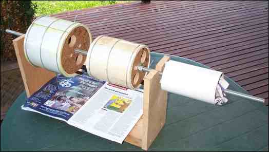
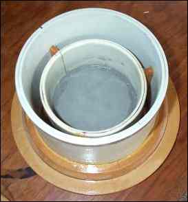
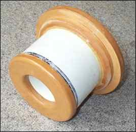
Jig Assembled
Disks mounted on some threaded rod make up the jig for holding the PVC whilst heating and gluing. The simple stand makes both operations much easier.
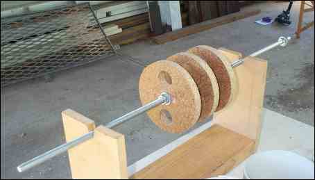
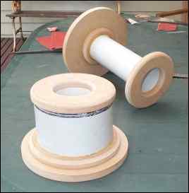
Ready for heating
A jig was made from some threaded rod and some chipboard disks. This shot shows a single layer about to be treated with the heat gun to relieve stress. Each layer is done this way before any gluing takes place
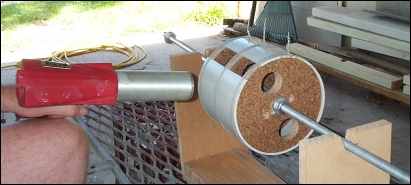
Applying the heat
A heat gun is used to soften the PVC to allow it to take on the diameter of the jig disks. Work side to side and turn the job a la spit roast
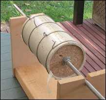
Epoxy drying
Two layers of PVC wired onto jig and glued with epoxy resin. Starting with 103mm sewer pipe and inserting strips, produces this 120mm composite tube. This will become the innermost tube of a concentric port
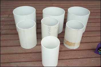
It takes this many...
These are the pieces for the 86mm test port to be used for the "chuff and resonance" tests.
The inner 86mm tube will use the single tube at the front.
The middle 124mm tube will be a composite made from two 103mm tubes plus strips from a third
The outer 163mm tube will be a composite made of two 152mm tubes plus strips from a third
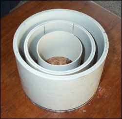
Tube comparison
Test port being glued. Inner layer added to shot to show the relative diameters of the tubes
Tubes cut to length
The finished composite tubes for the test port showing relative diameters and lengths
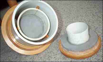
Main Pieces
The main pieces. The first of three supporting struts is about to be epoxied to the middle tube
Inner-outer
The inner and outer tubes, before the middle tube is slid into place from the front
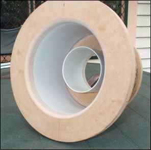
Middle and Outer
The middle and outer tubes epoxied in place. Foam damping piece visible in the centre
Damping in place
Damping fitted to endcaps. The rear cap will only be held in place with silicone sealant to allow removal later. This will be to replace the damping with a solid spacer of the same thickness to test the effectiveness of the damping in reducing the level of pipe mode resonance
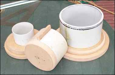
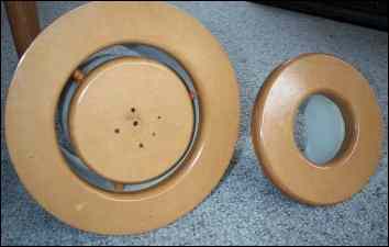
Front and back
This view shows the front and back endcaps, allowing you to see the size difference
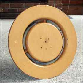
Front view
Front view of completed port, ready for installation in test box
Side view
Three quarter view of port showing flared intake port
Comparison
Concentric port compared with equivalent conventional port
Ready to use
Another view of the front