
Cleanbox
Why might I need one?
When connecting consumer level gear to pro-level amps, there is often not sufficient signal level to drive the pro gear to full output.
The line level for pro gear is around 12dB higher than that for consumer gear
An ART Cleanbox with up to 20dB gain, inserted between the source and the power amp will boost the signal level to what is required.
As an added bonus, the Cleanbox will convert the unbalanced RCA input to a balanced XLR output and vice-versa, meaning the following converter is no longer required
Note that there's also a Cleanbox II, which is just a pair of isolating transformers used for stopping earth loops. That's not what we're talking about here...
Using with a BFD
When using a BFD (Behringer Feedback Destroyer) filter unit, it is handy to use the LED level meter to monitor the signal level.
In an ideal setup, the yellow warning LED should just flicker as the maximum output of the subwoofer is reached.
The BFD has a choice of two sensitivity levels for the input: -10dB (most sensitive) or +4dB (less sensitive).
Whilst it looks like the difference is 14dB, the two are with respect to different standard levels. According to
this posting at AVSForum.com,
the actual difference is 11.79dB
Switching between the two changes the internal operating range, however the BFD is a unity gain device, so the output
will only be as strong as the input
When driving the BFD from a consumer-level source, the more sensitive input is often needed for the LEDs to display their full range.
When the LEDs indicate full signal, the actual output level is still at the consumer level.
Placing a Cleanbox before the BFD, and setting the BFD to the less sensitive input level, as shown in the following diagram, lifts the operation
to pro level, whilst retaining the use of the LED bargraph to monitor maximum output.
Connections
The RCA connectors on the front are the Left and Right inputs for Channel1 (this is a stereo capable device), and the outputs for Channel2
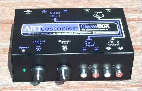
The XLR connectors on the back are the outputs for Channel1 and the inputs for Channel2
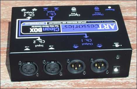
Block diagram underneath. Sturdy metal case comes with stick-on feet.
The most common usage for subwoofer application is to use either the Left or Right path of Channel 1 to convert from RCA unbalanced to XLR balanced.
Channel 2 converts in the opposite direction and less often required in this situation.
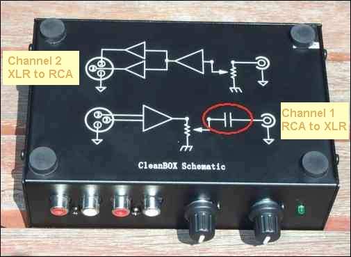
The factory block diagram is a bit confusing. Here it is redrawn to utilise standard circuit drawing conventions:
- Inputs on the left, outputs on the right, for both channels
- Channel 1 shown at the top
- Op-amps shown as an arrowhead with the output at the sharp end, requiring that...
- A second op-amp is shown for the XLR output to indicate that terminal2 and terminal3 are not the same

Using the Cleanbox for subwoofers operating below 30hz
The Cleanbox is designed for musician use, where the signal is not much below 30hz. The input capacitors shown circled in the above photo are for Channel1 (RCA to XLR conversion) and cause a dramatic insertion loss for just the frequencies treasured by subwoofer users! The reverse direction, (from XLR to RCA), doesn't have this problem.
| Frequency in hz | Insertion loss in dB |
| 100 | - 0.4 |
| 50 | - 1.5 |
| 20 | - 5.4 |
| 10 | - 10.3 |
| 5 | - 15.9 |
| 2 | - 22.6 |
Modification designed and promoted at The Home Theater Shack
Increasing the value of input capacitors from 0.047uF to 1.0uF will give a new response that is flat to below 10hz.
If you wanted, you could modify just the left signal path, and leave the right as a pseudo "high-pass" device. In this example, both the left and right paths were done
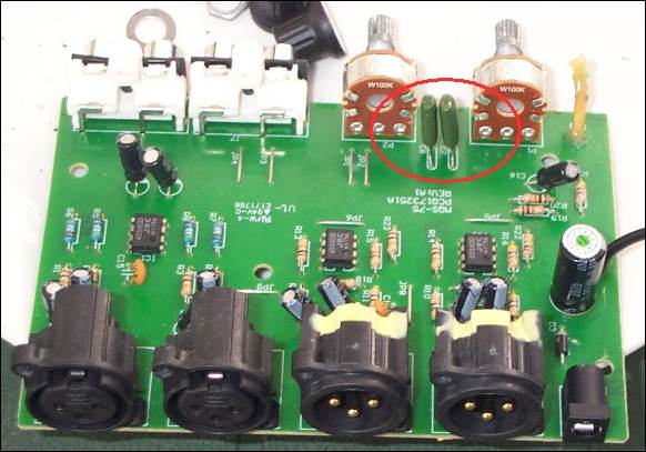
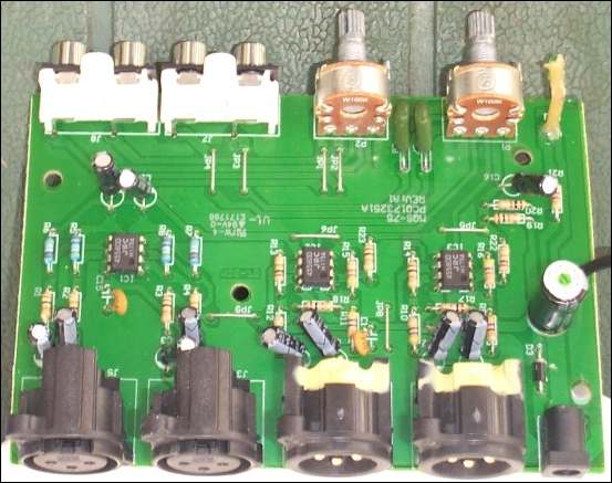
This is a very simple modification if you have a soldering iron. The original 0.047uF capacitors to be removed are shown circled in the next photo
New 1uF / 100v miniature polyester capacitors installed (Jaycar part no: RM7170 for Aussie coneheads)
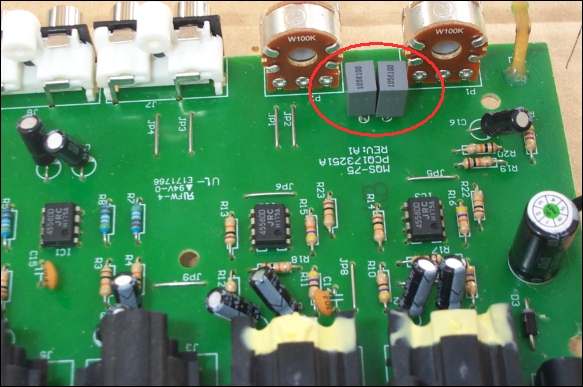
0.47uf or 0.68uf would have been OK too, as would 63V rated.
Do not used polarised caps such as tantalum or electrolytics. Greencaps and Polyester are OK
Track side
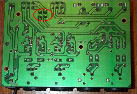
Here's a view you don't see everyday - tracks flipped and ghosted onto component side
Power supply
Early versions of the cleanbox came with a switch-mode plugpack. For installations where the signal shield is above earth, (eg double-earthed devices with any earthed ones connected via optical leads), this can introduce RFI noise. If there are problems with your tuner, changing to a transformer plugpack can fix it.
Cleanbox related links
Cleanbox modification discussion
Original source of suggested modification
Some info on +4 / -10 dB What are these levels anyway..?
Sound System Interconnection Rane note on balanced connections
Grounding and Shielding Audio Devices Rane note on balanced vs unbalanced connections
Alternative products
An alternative to the Cleanbox is the S-Convert from
Samson Audio
A tad more expensive, does the same job, but no mod required.
Our Kiwi cousins can buy the Get Up box
at Audioshop
If you build the high-pass filter detailed elsewhere on this site, and don't need the unbalanced to balanced conversion, you can include enough gain to do without a cleanbox