Active High Pass Filter
A ported subwoofer can lose control of the driver below the tuning frequency. Including a high pass filter in your design can protect the driver from potentially damaging over-excursion.
This page presents a design for an active hi-pass filter suitable for use with subwoofers, along with tips on how to determine the optimum design frequency using WinISD. Also presented is the downloadable Subsaver calculator for determining the component values,
Butterworth 12dB/octave high-pass filter
The Butterworth design was explored and refined in
this thread
at hometheatershack.com.
Particular thanks go to forum users Martin Sturm and neptuneEQ
for their support and expertise.
Design principles from the Linkwitz Labs website was the starting point for the design.
Thanks also go to good friend and electronics guru, Bob Worthington, who double checked the circuit and
beta-tested the software.
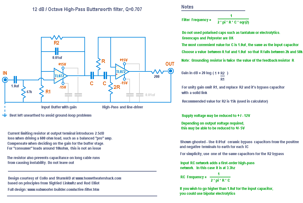
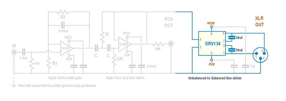
The following circuit and design notes were developed, and only require a single TL072 dual op-amp package, yet include the filter, line-driver, input buffer, and facilty to set the gain by choice of resistors
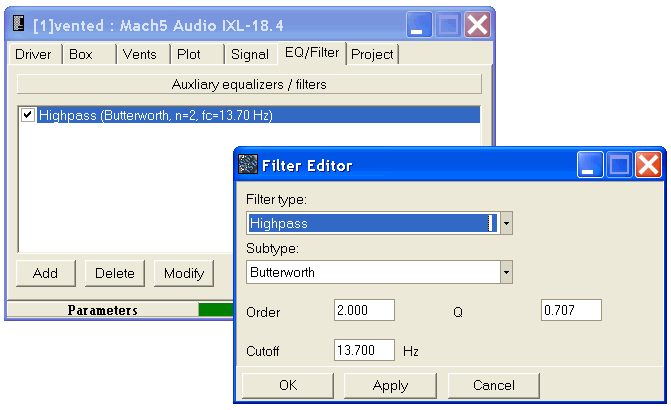
To choose the frequency for the filter, first add the filter to your design program. Here's how you do it in WinISD
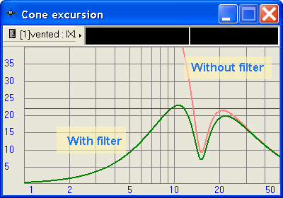
Adjust the frequency until the peak in cone excursion below the tuning point is less than Xmax + 10%. In the following example, Xmax is 22mm, so we're are aiming for 24mm or less
When modelling your filter, you should also include any other known rolloffs in your signal chain
User SturmMD measured his system and discovered the following:
EP2500: 1st order HPF at 4.1Hz
BFD: 1st order HPF at 3.7Hz
Receiver's sub output: 1st order HPF at 2.5Hz
This would give you the following filters in WinISD, all modelled as 1st-order Butterworth, with a Q of 0.707:
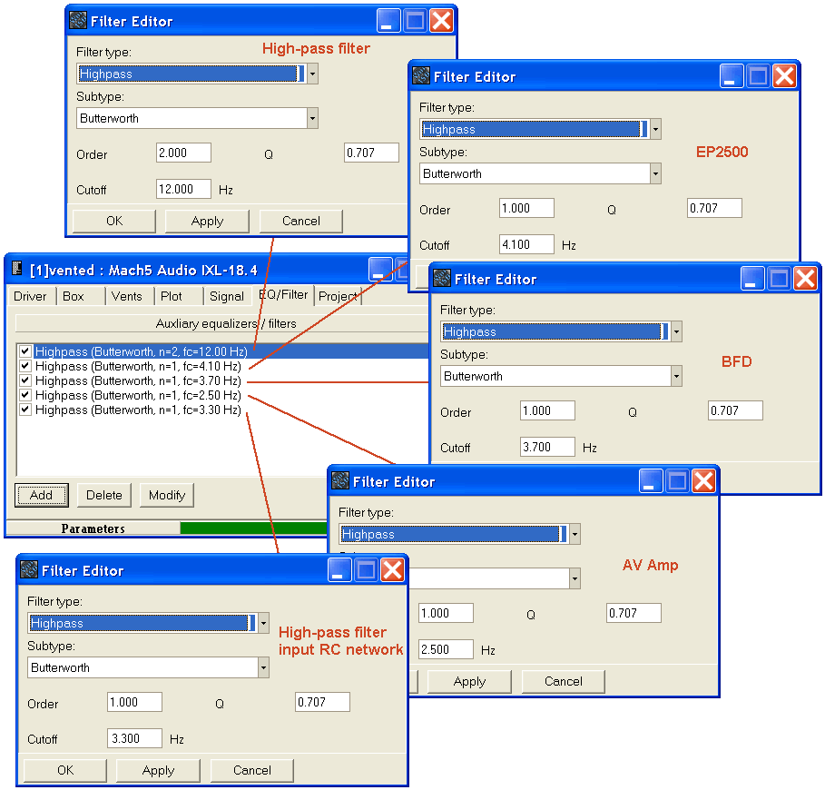
With all these in play, the required frequency for the high-pass filter in our example now shifts to 12hz to retain the control over cone excursion, without sacrificing more SPL than needed.
Component values
Having chosen the frequency for your filter, it's time to select the component values
By far, the easiest way to find these is to download the Subsaver calculator
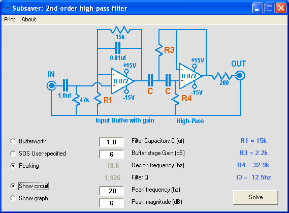
Subsaver screenshot - circuit view
Subsaver can model a normal Butterworth filter, as well as a peaking filter. Gain can be added to the design, with the final response presented as a graph. The three styles of filter correspond to those offered in WinISD. Generally, the standard Butterworth is all that you will need.
Provided you are running the full +/15V power supply (see below), it should be acceptable to model gain as high as 14.5dB. This is how much you would need to replace your cleanbox. 12dB to go from "consumer" level to "pro" level, and 2.5dB to make up for what is lost across the output resistor when driving a 600 ohm load
Power supply
The filter can be powered with a simple +/- 15V regulated supply kit
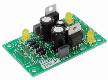
A centre-tapped transformer could be used, giving full-wave rectification.
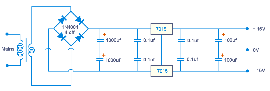
Powering the board with a 15VAC plugpack is easier and safer, keeping mains voltages out of your project.
The downside is it's a bit dearer and only gives half-wave rectification, so it would probably be worth upgrading the electrolytics
on the input side of the regulators to 4700uf, 25V

FAQ and Additional Circuit options
Q. What is the maximum gain that can be achieved?
This depends on the supply and input voltages
To maintain linearity, the output should not exceed 80% of the supply voltage.
Whilst it is possible to supply this circuit with 12V or even lower, the recommended value of 15V gives an allowable output of 12V peak or 8.49Vrms.
If driving from a "pro level" source, the operating level should be around 1.23 Vrms
If driving from a "consumer level" source, the operating level should be around 0.3 Vrms
In this case the maximum gain would be 29dB.
Since the output at this gain would be more than is needed to drive a "pro"
amp to full output, the maximum gain for the calculator has been set to 20dB
Thanks go to Bob Worthington for this erudite answer!
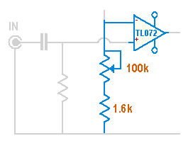
Q. How can the gain be made variable?
Subject to the input voltage constraints listed in the previous question, a range of 1.2dB gain thru 20dB gain can be achieved by replacing R1 with a fixed 1.6k resistor in series with a 100k potentiometer, wired as follows:
Q. How can the output be made balanced?
Whilst this is departing from the minimilist design, a balanced output stage can be tacked on the end using a DRV134 IC
The 10uf caps are non-polarised electrolytics. For more info, see the
manufacturer's data sheet (pdf)
Q. Why not balance the impedances into the first op-amp?
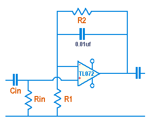
It is generally good practice to balance the input impedances to an op-amp where possible to reduce DC offset at the output. To achieve this in the buffer stage shown above, Rin should equal the value obtained if R1 and R2 were in parallel.
This was not done for three reasons....
- The buffer stage is coupled to the following stage by capacitors. This prevents any DC offset from being carried forward
- By making R2 fixed, the calculator no longer needs to ask the user for the value of Rin and R2, simplifying the program interface
- R2 has a 0.01uf bypass capacitor in parallel, causing a response pole calculated by f=1/(2*pi*R*C). It has been suggested that keeping this above 1kz is a good idea, which requires R2 to be no more than 15k. This is the value used in the calculator and recommended in the design notes
Q. What are the limits on values for each field in the calculator?
| Field | Minimum | Maximum |
| Filter Capacitors | 0.0001uf | 10uf |
| Buffer gain | 0dB | 20dB |
| Design Frequency | 1hz | 1000hz |
| Filter Q | 0.707 | 10 |
| Peak Frequency | 1hz | 1000hz |
| Peak Magnitude | 0dB | 20dB |
Linkwitz-Riley 24dB/octave high-pass filter
Whilst no longer recommended, the LR filter was used in the Sidewinder subwoofer, so it's details are included here.....
There are many active filter designs available, and one popular one is the Linkwitz-Riley filter, which has a rolloff of 24dB / Octave.
The filter is very similar to the one presented above, except it uses two Butterworth stages cascaded together to get the required rolloff.
A detailed discussion of this filter is available at the
Linkwitz Labs website, which suggests the following circuit.
Frequency = 1/(2 * pi * R * C * sqr(2))
For example R=20K C=0.33uF should yield 17Hz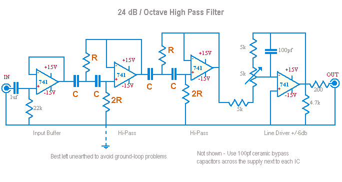
Be warned, the filter designer in WinISD has some faults - their circuit shows both resistors the same, rather than one being twice the value of the other as shown above. This has been acknowledged by the authors, so I guess it would be fixed in their next production release. Also it doesn't calculate the correct values, so use the formula above or double check with another package
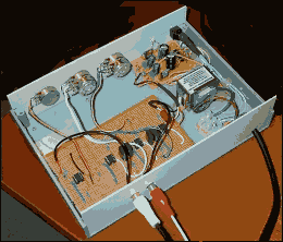
I made mine on some "Veroboard" - the extra pots were part of the experimental setup and were removed once the final values were settled on.
If you're good at maths, you can find a comprehensive article on filters at maxim-ic.com
Rane also has a good article about Linkwitz-Riley Crossovers
